Networked Arduino Heartbeat sensor + SuperCollider
19 Jul '09
I made a simple heartbeat sensor using an Arduino which sends OSC signals at each heartbeat over a network. I’m using the heartbeat sensor as an awesome prop in my show which is on at the Street Theatre in Canberra!
There’s a new video here.
And an article on Makezine here!
I got the idea from Recotana’s Heartbeat Midi Controller. Recotana also wrote the OSC library for Arduino which enabled this project. Networked Arduino Heartbeat Sensor Code (Requires Recotana’s OSC Library):
// cpm_heartbeatEthernet
// Version 1.0 October 2009.
// Copyright Charles Martin (http://www.charlesmartin.com.au).
// Uses recotana's OSCClass (http://www.recotana.com)
// Detect heartbeat using a light reading through skin
// On each beat, send an OSC message of the instantaneous
// heartrate.
#include "Ethernet.h"
#include "OSCClass.h"
// Pins
const int ledPin = 13;
const int sensePin = 0;
// LED blink variables
int ledState = LOW;
long ledOnMillis = 0;
long ledOnInterval = 50;
// Hearbeat detect variables
int newHeartReading = 0;
int lastHeartReading = 0;
int Delta = 0;
int recentReadings[8] = {0, 0, 0, 0, 0, 0, 0, 0};
int historySize = 8;
int recentTotal = 0;
int readingsIndex = 0;
boolean highChange = false;
int totalThreshold = 2;
// Heartbeat Timing
long lastHeartbeatTime = 0;
long debounceDelay = 150;
int currentHeartrate = 0;
// Ethernet and OSC information
byte serverMac[] = { 0xDE, 0xAD, 0xBE, 0xEF, 0xFE, 0xED };
byte serverIp[] = { 192, 168, 0, 99 };
int serverPort = 10000;
// byte gateway[] = { 192, 168, 0, 1 };
// byte subnet[] = { 255, 255, 255, 0 };
byte destIp[] = {192, 168, 0, 255};
int destPort = 3333;
char *topAddress = "/heartbeat";
OSCMessage recMes;
OSCMessage sendMes;
OSCClass osc(&recMes);
void setup() {
Ethernet.begin(serverMac , serverIp);
osc.begin(serverPort);
osc.flush();
sendMes.setIp( destIp );
sendMes.setPort( destPort );
sendMes.setTopAddress(topAddress);
// initialize the serial communication:
Serial.begin(9600);
// initialize the digital pin as an output:
pinMode(ledPin, OUTPUT);
}
void loop() {
// Turn off LED
digitalWrite(ledPin, LOW);
// Read analogue pin.
newHeartReading = analogRead(sensePin);
//Serial.println(newHeartReading);
//Calculate Delta
Delta = newHeartReading - lastHeartReading;
lastHeartReading = newHeartReading;
// Find new recent total
recentTotal = recentTotal - recentReadings[readingsIndex] + Delta;
// replace indexed recent value
recentReadings[readingsIndex] = Delta;
// increment index
readingsIndex = (readingsIndex + 1) % historySize;
//Debug
//Serial.println(recentTotal);
// Decide whether to start an LED Blink.
if (recentTotal >= totalThreshold) {
// Possible heartbeart, check time
if (millis() - lastHeartbeatTime >= debounceDelay) {
// Heartbeat
digitalWrite(ledPin, HIGH);
currentHeartrate = 60000 / (millis() - lastHeartbeatTime);
lastHeartbeatTime = millis();
// Print Results
//Serial.println("Beat");
if (currentHeartrate <= 200) {
Serial.println(currentHeartrate); // Send a serial message
sendMes.setArgs("i" , ¤tHeartrate); // Setup an OSC message
osc.sendOsc( &sendMes ); // Send the heartbeat OSC message
}
}
}
delay(10);
}
Here’s some older information about the process of making this sensor!
I wanted it to communicate with the computer and send data to SuperCollider. As a proof of concept, I’ve connected the Arduino to SuperCollider via a Processing script that translates serial data from the Arduino into OSC messages. Here’s a video demonstration:
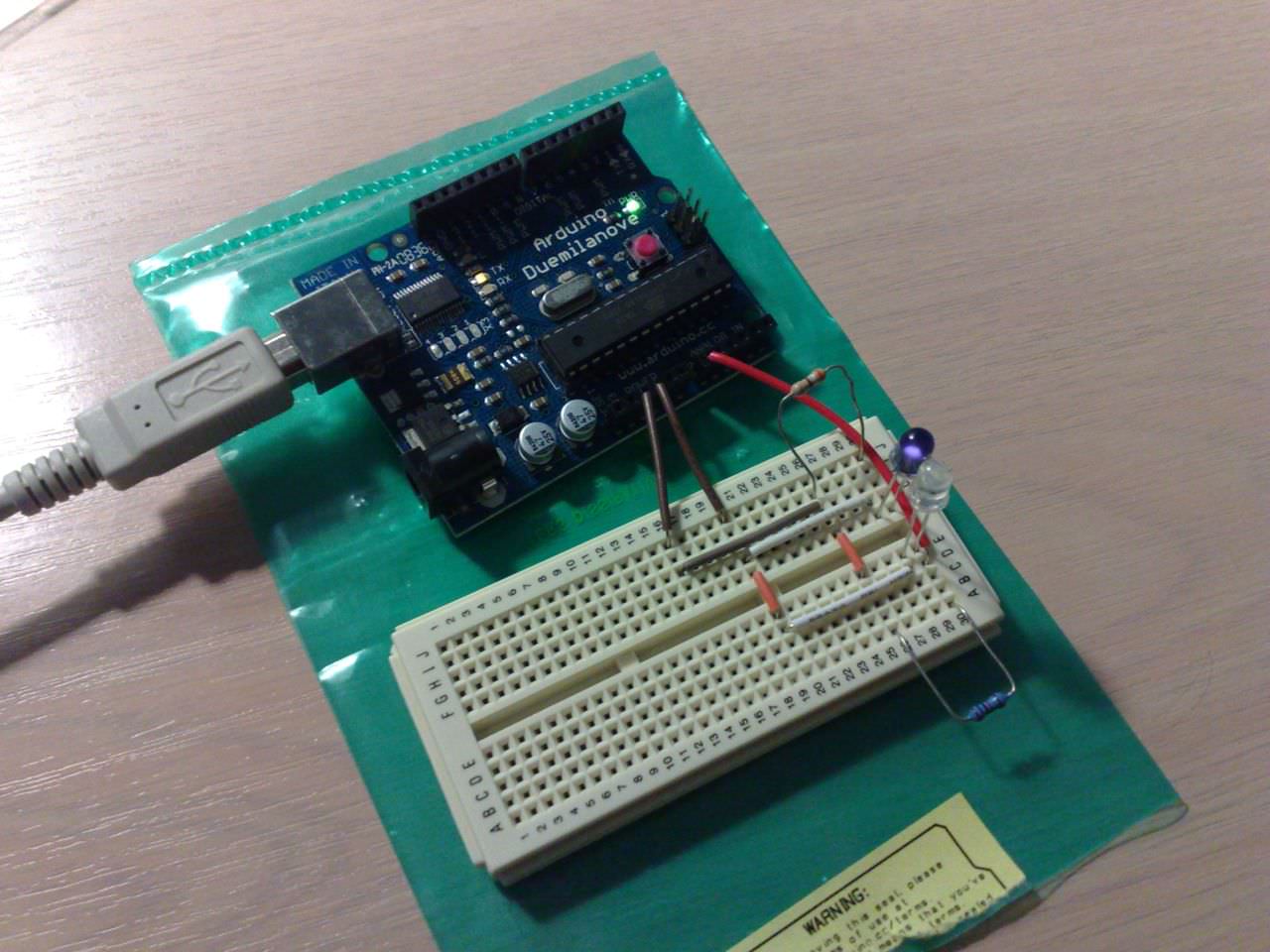
Arduino and the sensor circuit. My phone camera can see in infrared.
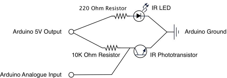
The sensor uses two simple components, an IR LED and an IR phototransistor. Both components are powered by the Arduino’s 5V output and one analogue input reads the voltage across the phototransistor.
- IR LED (Jaycar ZD1945)
- IR Phototransistor (Jaycar ZD1950)
- 10KOhm resistor
- 220Ohm resistor
The simple circuit is the same as for an IR range sensor, commonly used in robot projects. The easiest way to start looking at data form an Arduino’s analogue input is to follow the Arduino Graph tutorial.
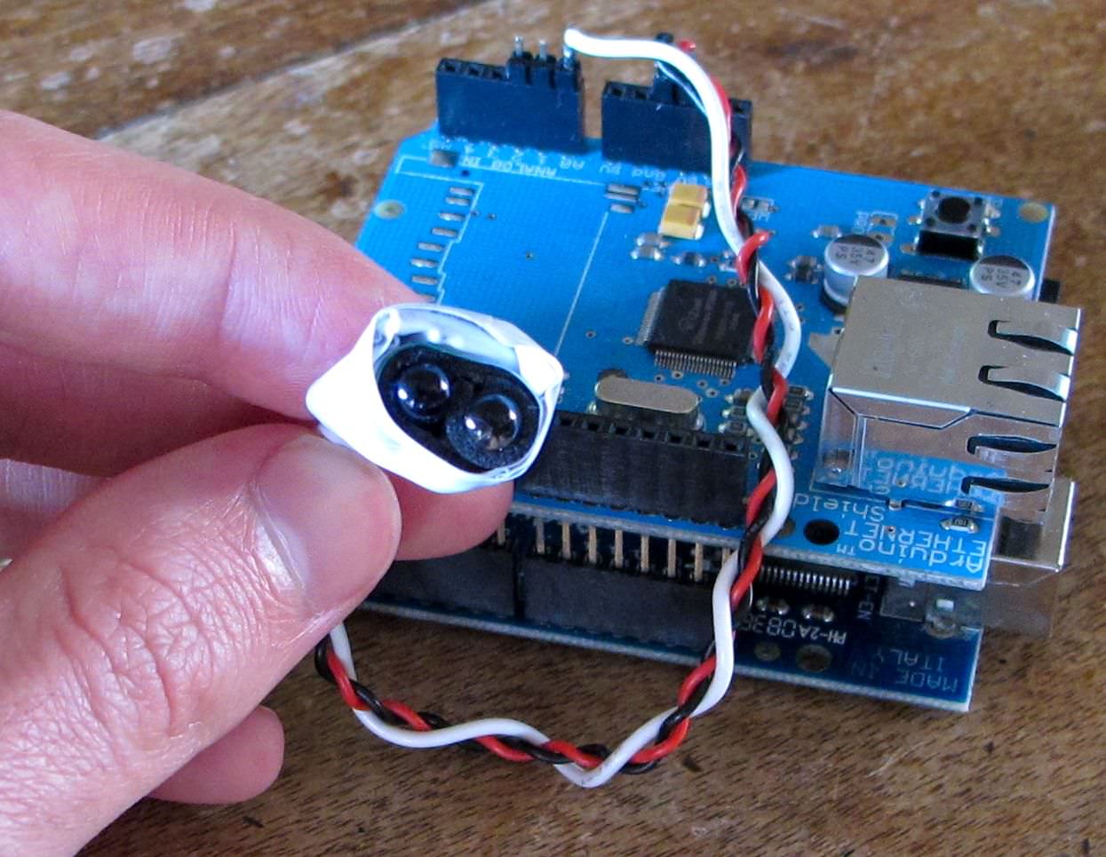
The idea is that when your heart beats you have a quick rush of blood into tiny blood vessels close to your skin which makes it less transparent. This effect is easiest to observe on your finger tips or earlobe. So the IR emitter and phototransistor are placed next to each other (not much light goes through the side of the emitter!) and I put my finger on top. Light from the IR emitter illuminates my skin and is reflected into the phototransistor.
The phototransistor is connected to the Arduino in a similar way to a potentiometer. One lead is connected to +5V and the other to ground. The +5V lead is also connected to an analogue input on the Arduino. When the phototransistor receives more IR light it becomes more resistive and a lower voltage is detected by the analogue input.
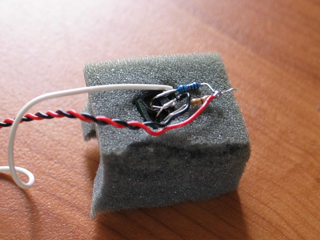
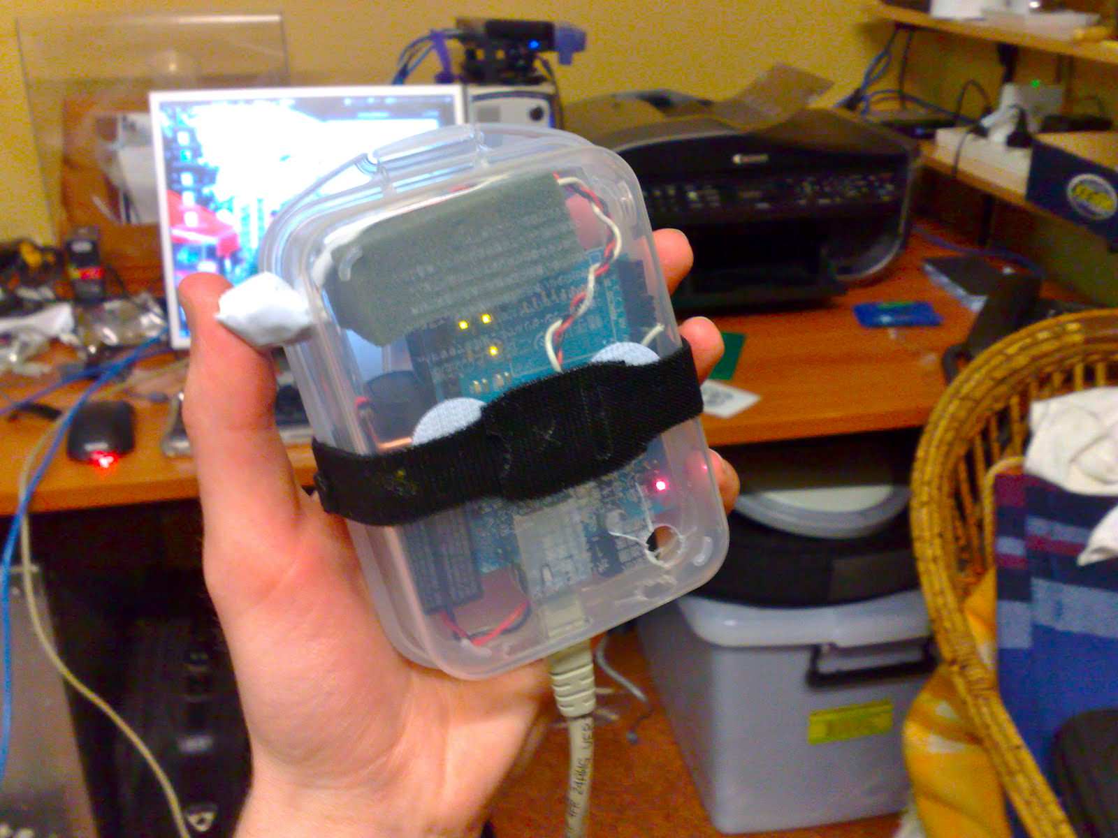
The circuit all soldered together and held together with double sided tape. It was then wrapped up in electrical tape to protect it and shield the phototransistor from other light sources.

Graph of the sensor output! Each little bump is a heartbeat!
Similar projects around the internet have used an amplifier to boost the signal from the phototransistor. I found that the data was clear enough for the Arduino to track heartbeats accurately. My Arduino program follows the (average) rate of change of the phototransistor voltage and uses this to judge whether a heartbeat is occuring or not.
Arduino Heartbeat Sensor from Charles Martin on Vimeo.
Arduino code:
// Pins
const int ledPin =  13;
const int sensePin = 0;
// LED blink variables
int ledState = LOW;
long ledOnMillis = 0;
long ledOnInterval = 50;
// Hearbeat detect variables
int newHeartReading = 0;
int lastHeartReading = 0;
int Delta = 0;
int recentReadings[8] = {0, 0, 0, 0, 0, 0, 0, 0};
int historySize = 8;
int recentTotal = 0;
int readingsIndex = 0;
boolean highChange = false;
int totalThreshold = 2;
// Heartbeat Timing
long lastHeartbeatTime = 0;
long debounceDelay = 150;
int currentHeartrate = 0;

void setup() {
  // initialize the serial communication:
  Serial.begin(9600);
  // initialize the digital pin as an output:
  pinMode(ledPin, OUTPUT);
}

void loop() {
  // Turn off LED
  digitalWrite(ledPin, LOW);
  // Read analogue pin.
  newHeartReading = analogRead(sensePin);
  //Serial.println(newHeartReading);
  //Calculate Delta
  Delta = newHeartReading - lastHeartReading;
  lastHeartReading = newHeartReading;
  // Find new recent total
  recentTotal = recentTotal - recentReadings[readingsIndex] + Delta;
  // replace indexed recent value
  recentReadings[readingsIndex] = Delta;
  // increment index
  readingsIndex = (readingsIndex + 1) % historySize;
  //Debug
  //Serial.println(recentTotal);
  // Decide whether to start an LED Blink.
  if (recentTotal >= totalThreshold) {
    // Possible heartbeart, check time
    if (millis() - lastHeartbeatTime >= debounceDelay) {
      // Heartbeat
      digitalWrite(ledPin, HIGH);
      currentHeartrate = 60000 / (millis() - lastHeartbeatTime);
      lastHeartbeatTime = millis();
      // Print Results
      //Serial.println("Beat");
      if (currentHeartrate <= 200) {
        Serial.println(currentHeartrate);
      }
    }
  }
  delay(10);
}
Processing code:
// Based on examples from Arduino's Graphing Tutorial and OscP5 documentation
import processing.serial.*;
Serial myPort;        // The serial port
int xPos = 1;         // horizontal position of the graph
import oscP5.*;
import netP5.*;
OscP5 oscP5;
NetAddress myRemoteLocation;
void setup () {
  // set the window size:
  size(640, 480);
  frameRate(25);
  // Start OscP5
  oscP5 = new OscP5(this, 12000);
  // List availabl serial ports.
  println(Serial.list());
  // Setup which serial port to use.
  // This line might change for different computers.
  myPort = new Serial(this, Serial.list()[0], 9600);
  myPort.bufferUntil('\n');
  // Configure NetAddress to send OSC messages to
  myRemoteLocation = new NetAddress("127.0.0.1", 57120);
  // set inital background:
  background(0);
}

void draw () {
}

void serialEvent (Serial myPort) {
  // read the string from the serial port.
  String inString = myPort.readStringUntil('\n');
  if (inString != null) {
    // trim off any whitespace:
    inString = trim(inString);
    // convert to an int
    println(inString);
    int currentHeartrate = int(inString);
    if (currentHeartrate > 0) {
      // Construct and send OSC message of the current heartrate
      OscMessage myMessage = new OscMessage("/heartbeat");
      myMessage.add(currentHeartrate);
      oscP5.send(myMessage, myRemoteLocation);
      // draw the Heartrate BPM Graph.
      float heartrateHeight = map(currentHeartrate, 0, 200, 0, height);
      stroke(127, 34, 255);
      line(xPos, height, xPos, height - heartrateHeight);
      // at the edge of the screen, go back to the beginning:
      if (xPos >= width) {
        xPos = 0;
        background(0);
      } else {
        // increment the horizontal position:
        xPos++;
      }
    }
  }
}

/* incoming osc message are forwarded to the oscEvent method. */
void oscEvent(OscMessage theOscMessage) {
  /* print the address pattern and the typetag of the received OscMessage */
  print("### received an osc message.");
  print(" addrpattern: "+theOscMessage.addrPattern());
  println(" typetag: "+theOscMessage.typetag());
}
SuperCollider Code:
// create the OSCresponder
// Beeps each time it receives a heartbeat OSC message.
(
n = NetAddr.new("127.0.0.1", nil);
o = OSCresponder.new(n, "/heartbeat", {
    arg time, resp, msg;
    msg.postln;
    { EnvGen.kr(Env.perc, 1.0, doneAction: 2) * SinOsc.ar([440,440], 0, 0.1) }.play;} ).add;
)

o.remove; // remove the OSCresponder.